
Refraction of Light through Rectangular Glass Slab
Refraction of Light through Rectangular Glass Slab
Aim
To trace the path of a ray of light passing through a rectangular glass slab for different angles of incidence, measure the angle of incidence, angle of refraction, and angle of emergence, and interpret the result.
Apparatus and Material Required
A rectangular glass slab, drawing board, white sheets of paper, drawing pins, four optical pins, a protractor, a scale, a pencil, and a sharpener.
Principle
When a ray of light travels from a rarer medium (air) to a denser medium (glass), it bends towards the normal. When it emerges from the denser medium back into the rarer medium (glass to air), it bends away from the normal.
- Angle of incidence (∠i): The angle between the incident ray and the normal at the point of incidence (on the first surface).
- Angle of refraction (∠r): The angle between the refracted ray and the normal inside the glass slab.
- Angle of emergence (∠e): The angle between the emergent ray and the normal at the point of emergence (on the second surface).
For a rectangular glass slab, since the two refracting surfaces are parallel to each other, the emergent ray is always parallel to the incident ray, though it is laterally displaced from it. This lateral shift is called lateral displacement.
Also, according to Snell’s law, for a given pair of media:

This ratio remains constant for all angles of incidence for the same slab.
Ray Diagram
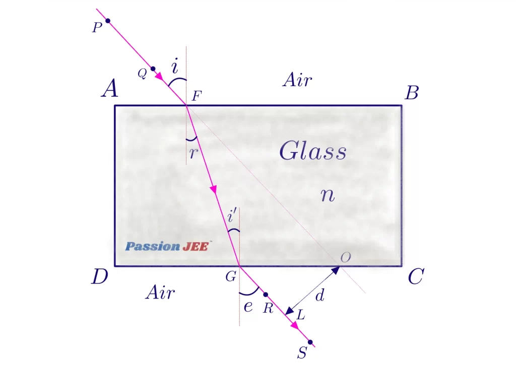
Procedure
- Fix a white sheet of paper on the drawing board using drawing pins.
- Place the rectangular glass slab in the middle of the paper and draw its outline (boundary ABCD) using a pencil.
- Remove the slab. At point O on side AB, draw a normal (NN′) perpendicular to AB.
- Draw a straight line making a chosen angle of incidence (e.g., 30°) with the normal — this represents the incident ray. Mark this angle as ∠i.
- Replace the glass slab exactly on its outline. Fix two pins, P₁ and P₂, on the incident ray line, about 5 cm apart, vertically upright.
- Looking through the opposite face (CD) of the slab, fix two more pins P₃ and P₄ such that they appear to be in a straight line with the images of P₁ and P₂ as seen through the glass.
- Remove the pins and the slab. Join the points P₃ and P₄ and extend the line to meet side CD — mark this point as O′. Join O and O′ — this represents the refracted ray path inside the glass.
- Join O′ with P₃, P₄ direction extended outward — this gives the emergent ray.
- Draw the normal at O′ on face CD.
- Measure the angle of refraction (∠r) between the refracted ray OO′ and the normal at O; measure the angle of emergence (∠e) between the emergent ray and the normal at O′.
- Repeat the entire procedure for different angles of incidence (e.g., 30°, 45°, 60°) and tabulate the readings.
- Verify that the emergent ray is parallel to the incident ray in each case, and note the lateral displacement.
Observations
| S.N. | Angle of Incidence (∠i) | Angle of Refraction (∠r) | Angle of Emergence (∠e) | sin i | sin r | sin i / sin r |
|---|---|---|---|---|---|---|
| 1. | 30° | 19° | 30° | 0.500 | 0.326 | 1.53 |
| 2. | 45°° | 27° | 45° | 0.707 | 0.454 | 1.56 |
| 3. | 60° | 35° | 60° | 0.866 | 0.574 | 1.51 |
Mean value of sin i / sin r ≈ 1.53 (this gives the approximate refractive index of glass,

Results
- In each case, the angle of incidence (∠i) is found to be equal to the angle of emergence (∠e), i.e., ∠i = ∠e.
- The emergent ray is found to be parallel to the incident ray, but laterally displaced.
- The ratio sin i / sin r is found to be nearly constant for all angles of incidence, verifying Snell’s law of refraction.
- The refractive index of the given glass slab, n = 1.53 (approx.) (sample value; typical range 1.5 – 1.52).
Interpretation
- Since ∠i = ∠e for every trial, and the incident and emergent rays are parallel, it is verified that a rectangular slab does not change the direction of the ray — it only shifts it laterally.
- The constancy of sin i / sin r confirms Snell’s law and gives the refractive index of the material of the slab.
- As the angle of incidence increases, the lateral displacement also increases.
Precautions
- The pins should be fixed vertically (perpendicular to the paper) and pressed firmly.
- The distance between any two pins should not be too small (to avoid errors in judging direction) or too large (to avoid inconvenience); about 5–6 cm is ideal.
- Points marking pin positions should be marked with sharp encircled dots (⊙), and thin, sharp pencil lines should be used.
- While viewing through the slab to fix P₃ and P₄, both eyes should be used with one eye closed, and all four pins should appear collinear.
- The boundary of the slab should be traced accurately, and the slab should be placed exactly within its outline throughout.
- The angle of incidence should not be taken as 0° or 90°, and should not exceed 90°.
- The normal must be drawn accurately at exactly 90° to the refracting surface.
Sources of Error
- Pin pricks on paper may not be point-sized, causing slight error in joining points.
- Human error/parallax in aligning pins with the image seen through the glass.
- The glass slab surfaces may not be perfectly plane or parallel.
- Errors in measuring angles with the protractor.
Viva questions on Refraction through Glass Slab, Click Here
For more practical records in Science Practical Class 10, Click here
For more practical records in Practical Records for Class 11, Click here
For more practical records in Physics Practical Class 12, Click here
For Viva questions on Physics Practical Class 12, Click here